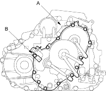
- Install the end cover (A) with the two dowel pins, new O-rings, new gasket and connector bracket (B). Tighten the 12 bolts to 12 Nm (1.2 kgf/m, 8.7 lbf/ft).

- Set the control shaft (A) to
 position by turning it.
NOTE: Be careful not to squeeze the end of the control shaft tips together when turning the shaft. If the tips are squeezed together it will cause a faulty signal or position due to the play between the control shaft and the switch.

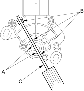
- Align the cutouts (A) on the rotary-frame with the neutral positioning cutouts (B) on the transmission range switch, then put a 2.0 mm (0.08 in.) feeler gauge blade (C) in the cutouts to hold it in the
 position.
NOTE: Be sure to use a 2.0 mm (0.08 in.) blade or equivalent to hold the switch in the  position.

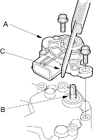
- Install the transmission range switch (A) gently on the control shaft (B) with holding the
 position with the 2.0 mm (0.08 in.) blade (C).


